A tripping breaker, hot busbar, missing phase, or unstable control circuit needs a controlled diagnosis rather than a quick reset or component swap. By the end, you will have a safe fault-finding sequence, measurement checklist, and clear boundary between work an authorised plant electrician can perform and work that requires an industrial electrical equipment manufacturer.
Key takeaways
- Confirm the panel voltage boundary before inspection or measurement.
- Isolate, lock out, test for dead, and discharge stored energy before opening.
- Use visual checks, electrical readings, and thermal evidence in sequence.
- Escalate damaged busbars, insulation, protection settings, or recurring faults to the manufacturer.
Make the LT Panel Safe Before You Open It
Before any inspection or measurement, confirm the LT assembly’s voltage boundary from its nameplate and drawings. IEC 61439 covers assemblies up to 1,000 V AC or 1,500 V DC; never assume the panel is within that limit.
1. Identify every source: incomers, bus couplers, generators, UPS systems, capacitor banks, control transformers, and possible backfeeds. Isolate each source, apply lockout/tagout, and attach clear tags.
2. Control stored and induced energy. Discharge capacitor banks using the specified procedure and wait for documented discharge; an open incomer does not prove that the panel is dead.
3. Prove de-energization with a correctly rated, functioning tester. Test the tester on a known live source, test every relevant conductor, then test the instrument again on the known live source. Investigate any unexpected reading.
4. Establish the site-defined arc-flash boundary and wear the PPE specified by the electrical-safety procedure. Live testing is limited to competent, authorised personnel using an approved method and insulated, correctly rated equipment.
A missing barrier, exposed terminal, defeated door interlock, or bypassed shutter is a safety defect, not a cosmetic issue. Stop the job and correct or escalate it before opening the enclosure; an industrial electrical equipment manufacturer may be needed when the safety arrangement or assembly construction is compromised.
Follow a Fault-Finding Sequence Instead of Guessing
Trace the symptom to the failed section by recording the event before touching the breaker. Note which breaker operated, whether it indicated long-time, short-time, instantaneous, or earth-fault operation, the alarm history, the load running, and any smell, noise, flash marks, or recent work. Review the single-line diagram, wiring diagram, protection schedule, and panel nameplate.
Follow this sequence:
- Inspect busbars, cable lugs, terminals, contactors, overload relays, neutral links, control fuses, interlocks, and outgoing feeders for loose terminals, overheating, phase loss, insulation breakdown, or control-circuit faults.
- Where safe and authorised, test incoming line-to-line and line-to-neutral voltage, phase current on each phase, protective-conductor continuity, outgoing-circuit condition, and the connected load.
- Segment the suspected circuit before insulation testing; a low reading alone does not identify whether the feeder, cable, motor, or panel wiring has failed.
- Do not reset repeatedly, install a larger breaker, or replace a breaker until you identify its trip mechanism.
| Reported condition | Likely direction | Confirm by checking |
|---|---|---|
| Long-time trip | Overload or poor coordination | Load current, settings, cable rating |
| Instantaneous trip | Downstream short circuit | Cable, terminals, contactor, load |
| Earth-fault trip | Earth leakage or insulation failure | Protective conductor and insulation |
| Contactor chatter | Low control voltage or control fault | Control fuse, coil voltage, interlock |
| Unequal phase current | Phase loss or voltage imbalance | All phase voltages and connections |
| Hot joint or busbar | Loose connection or overload | Torque, loading, thermal comparison |
These LT control panel faults require evidence, not guesswork. A breaker that trips repeatedly may be protecting the equipment rather than failing itself.
Use Readings and Thermal Evidence to Locate the Failure
Record each line-to-line voltage, line-to-neutral voltage, phase current, continuity result, earth-continuity result, insulation-resistance test voltage and duration, and protective-device setting. Compare every value with the panel nameplate, cable ampacity, breaker rating and interrupting capacity, motor full-load current, and calculated design load.
- Treat a loose or open neutral as a separate fault. Phase-to-phase voltage can remain normal while phase-to-neutral voltage shifts and damages single-phase loads.
- Measure neutral heating under load. Switch-mode power supplies and LED drivers generate triplen harmonics that add in the neutral instead of cancelling.
- Before megohmmeter testing, disconnect drives, electronic trip units, PLC inputs, power supplies, meters, surge-protection devices, and other sensitive equipment as their documentation directs.
- Segment the test into feeder, bus section, cable, motor, and control circuit. A low reading alone does not locate the defect; moisture, contamination, cable length, and connected suppressors also reduce insulation resistance.
Thermal imaging is useful only when you compare equivalent terminals, busbar joints, cable lugs, and contactors under meaningful load. A cool image at light load does not prove a sound connection.
| Evidence | Compare or confirm | What it indicates |
|---|---|---|
| Voltage and current | Nameplate, design load, motor full-load current | Phase loss, imbalance, overload, or neutral shift |
| Thermal image | Equivalent loaded connection points | Abnormal resistance or uneven loading |
| Torque check | Manufacturer’s specified value | Loose or over-tightened termination |
| Insulation result | Segmented circuit and recorded test conditions | Feeder, cable, motor, or control fault |
Confirm torque from the component or panel manufacturer and use a calibrated torque tool. Never substitute a generic value during LT panel maintenance.
Decide Whether an Electrician Can Repair It or a Manufacturer Must
An authorised plant electrician can handle a documented field-level correction; an industrial electrical equipment manufacturer for LT panel repair must assess any assembly-level change. The dividing line is whether the work alters the panel’s verified construction or protection.
- Correct a loose termination with the specified torque, after confirming the connection and drawing.
- Replace a like-for-like control fuse or contactor only after verifying ratings, wiring, and coil voltage.
- Clear a confirmed downstream overload, repair an identified field cable, or restore a documented control connection.
- Refer faults involving busbars, busbar supports, barriers, enclosure distortion, breaker mounting, altered wiring, protection coordination, or protective-device changes.
- After a short circuit, inspect for arc products, insulation tracking, contact damage, damaged lugs, distorted metalwork, and weakened supports. Cleaning alone does not prove recovery.
- Reject a replacement breaker unless its voltage, pole arrangement, mounting system, trip characteristics, interrupting capacity, prospective short-circuit current, and coordination match the design.
IEC 61439 covers assemblies up to 1,000 V AC or 1,500 V DC. Changing busbars, clearances, creepage, enclosure arrangements, or protective equipment can alter verified temperature-rise and short-circuit-withstand characteristics. A higher breaker rating can defeat upstream discrimination and create a fire risk.
Sneh Raman Electricals Pvt Ltd can help assess whether a damaged LT assembly needs component replacement, repair, or a new verified build rather than a cosmetic reset. Use an industrial electrical equipment manufacturer when the fault crosses from a replaceable component into the assembly’s design.
Related products
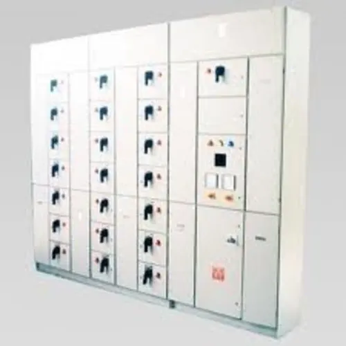
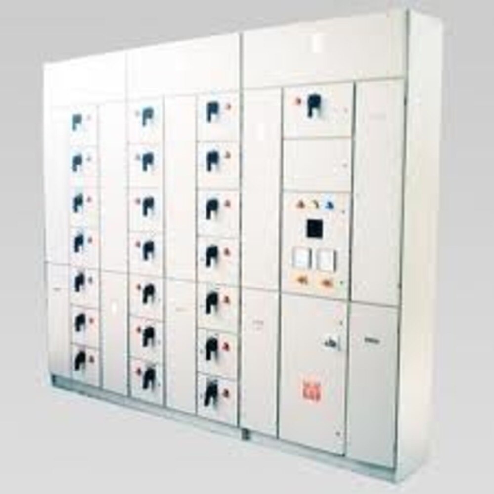
 | LT Distribution Panel We are successfully meeting the varied requirements of our clients by providing the best quality range of LT Control Panel. View product → |
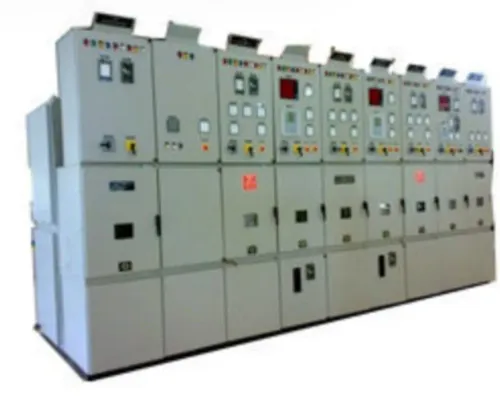
 | Meter Panel Board 3 - Phase Metering Distribution Panel Being a leader in the industry, we are engaged in offering a qualitative range of Metering Distribution Panel to our customers. View product → |
Restore Service, Prove the Repair, and Track Recurrence
Do not accept “the motor started” as proof of repair. Compare the restored panel with approved drawings, original nameplate ratings, and recorded pre-fault settings before declaring service.
1. Verify phase sequence, line-to-line voltage, line-to-neutral voltage, and protective-conductor continuity. Confirm each breaker operates correctly, including shunt trip and undervoltage release functions where fitted.
2. Test interlocks, door controls, shutters, barriers, indication lamps, alarm contacts, trip contacts, and metering polarity. Any exposed live part, defeated interlock, missing shroud, or incorrectly reconnected control circuit prevents acceptance, even when the equipment runs.
3. Energise in a controlled sequence. Test each outgoing circuit individually, then monitor phase current and temperature while the connected load operates. Record unresolved defects; do not close the job with open corrective actions.
4. Make LT panel maintenance risk-based rather than calendar-only. Record load and phase-current trends, breaker operations and trip causes, thermographic findings, torque or connection checks, insulation tests, protection settings, functional interlock tests, and repair history.
5. Review those records after every event. Repeated overload, phase imbalance, harmonic heating, poor coordination, or an undersized design points to a recurring system problem; one failed contactor or breaker points to an isolated component failure. A trend prevents repeated resets from hiding the same fault.
Frequently asked questions
How do you make an LT panel safe before opening it?
Confirm the nameplate and drawings, isolate every supply, apply lockout and tagout, test for absence of voltage, and discharge stored energy before opening the assembly.
What fault-finding sequence should you follow for LT control panel faults?
Start with the incident history and visible damage, then check incoming power, protective devices, control circuits, connections, loads, and interlocks without guessing or replacing parts at random.
Which readings and evidence help locate an LT panel failure?
Compare phase-to-phase and phase-to-earth voltage, measure continuity and insulation resistance when appropriate, and use thermal evidence to identify overloaded or high-resistance connections.
When should you call an electrician or industrial electrical equipment manufacturer?
Call a qualified electrician for safe isolation, testing, and routine component replacement. Contact the manufacturer for damaged busbars or insulation, protection coordination issues, design changes, recurring faults, or unknown short-circuit conditions.
How do you prove an LT panel repair and track repeat faults?
Recheck torque, wiring, protection settings, insulation, phase sequence, interlocks, and load performance; record readings, replaced parts, fault conditions, and recurrence dates before returning the panel to service.
Related product
 | Distribution Board We are successfully meeting the varied needs of our patrons by offering a wide gamut of Distribution Board as per their precise needs. View product → |